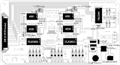
This interface is designed for use with a three axis robot arm based on stepper motors out of 5 1/4" drives. The circuit uses two ULN2803 'drivers' controlled by logic ICs to allow mutliple lines to be controlled at the same time. (Logic circuit design by Ian Threlfo). How it Works: Click here for an explanation of the circuit logic.
This is also the first interface bearing the Educational Computing Association of Western Australia (ECAWA) logo, indicating it has been developed by the ECAWA Robotics Special Interest Group.
Logic Design
Component Overlay
Parts List
2 x 4081 AND gate
2 x 4030 NOR gate
2 x ULN2803 Driver
1 x 74LS244 buffer
12 x 560 ohm resistor
12 x 100Kohm resistor
1 x 10Kohm resistor
1 x 47 uF electrolytic capacitor
1 x 2.1mm power socket
1 x DB25 PCB mount, right angle socket
1 x serial cable (male to male)
1 x 1 amp bridge rectifier
1 x 7805 voltage regulator
1 x 7812 voltage regulator
12 x 3mm red LEDs
2 x 0.01 uF greencap capacitors
1 x PCB


No comments:
Post a Comment